source code clock
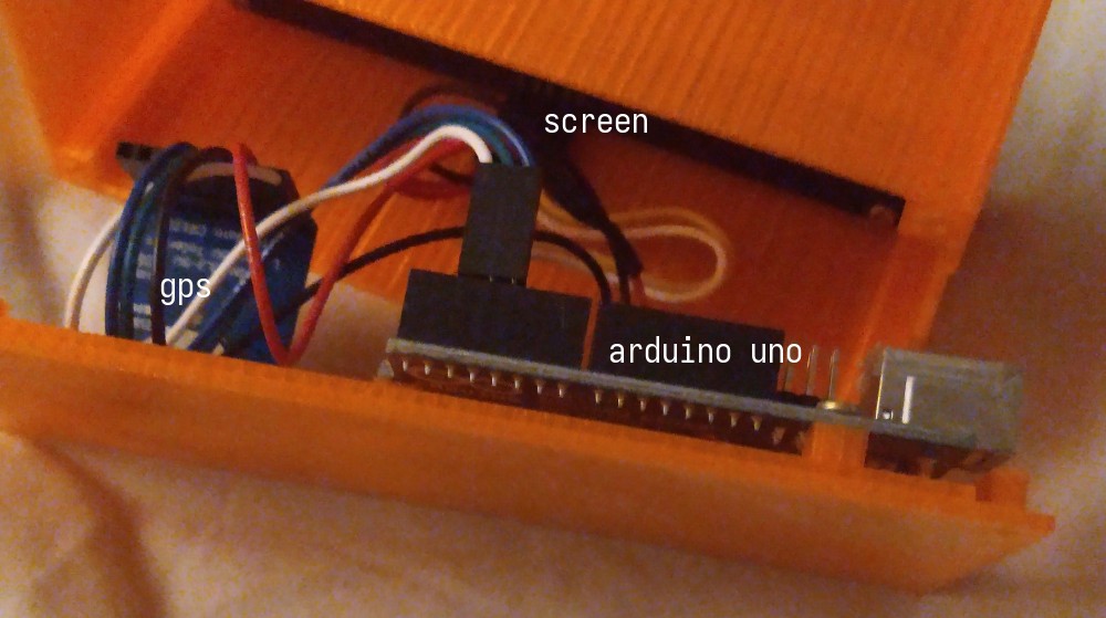
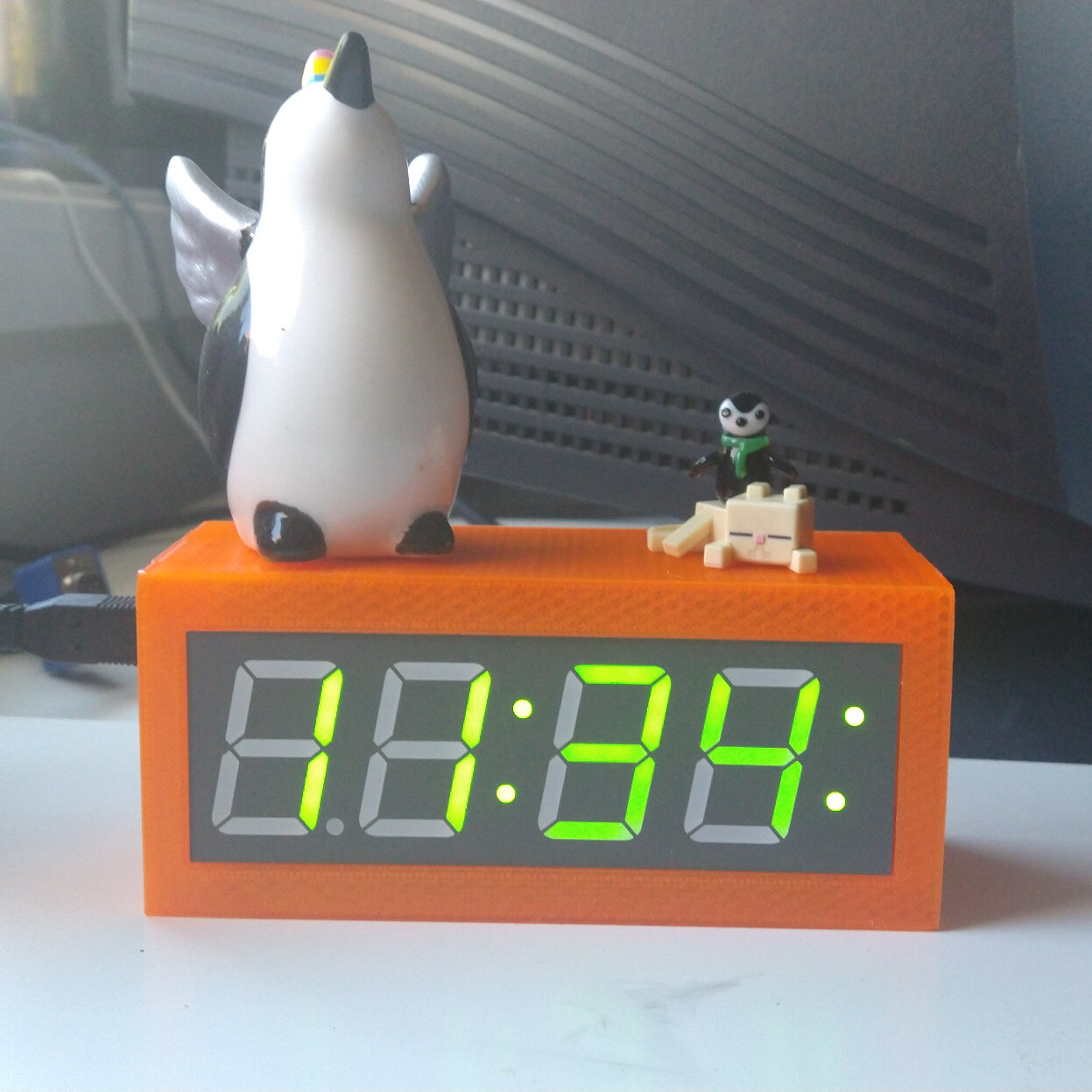
— in which i rewrite a clocka few years ago my dad and i made this clock:

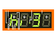
and by “my dad and i” i mean “my dad made it and i watched”, his making also involved him programming the clock. over the years since then i’ve grown to dislike the 12-hour formatting on the clock, as i use 24-hour for all the clocks in my computers and it really stuck out against them. ideally i’d make something like:

but i don’t really wanna buy four seven-segment displays for that. with the original clock however, it turned out that dad lost the source code for it (reasonable as it was already a finished thing), so in order to change anything about it i’d need to get a new source code
attempt 1: try and reverse-engineer the existing binary
as it turns out, with avrdude (the tool for flashing avr microcontrollers, like the one in the arduino) you can read the current program from the chip into a file, doing so gave me this 32KiB dump, however i’m lazy and can’t be bothered to learn how avr assembly works or figure out how to decompile it back to vague c++ (also doesn’t help that like all embedded projects are -Os since you’ve got very little flash space).
feel free to try and reverse-engineer it yourself, however i instead chose to just write a new source for it
attempt 2: rewrite it in rust
but first: a quick list of the hardware:
- an entire arduino uno, might as well just be a atmega328p with a weird pinout
- an adafruit 7-segment display with an i²c connection
- an adafruit gps thing which connects via 9600-baud serial
- the one thing i did make, a 3d-printed case for the thing, although entirely irrelevant for this
i thought it’d be funny to try and use embedded rust for for this, setting up a basic arduino-hal and ht16k33 project, i got it to cycle turning on the all the segments, but if i added the line to turn them off the compiled binary would be too large to flash to the board, and given that it was probably around 2 or 3 in the morning by then i decided to just give up.
attempt 3: rewrite it in rust c
might as well try raw avr c, so that i’m not reliant on needing the arduino ide to work to make things, might as well get some useful learning out of this project.
first step is to setup a dev environment:
{ pkgs ? import <nixpkgs> { } }:
pkgs.mkShell rec {
  buildInputs = with pkgs; [
    gnumake
    avrdude
    screen
    pkgs.pkgsCross.avr.buildPackages.gcc
  ];
}
TARGETS = target/main.o # …

CFLAGS = -Wall -Wextra -std=c99 -pedantic -Wno-array-bounds
CFLAGS += -DF_CPU=16000000UL # …

screen: program
        screen ${DEV} 9600

program: build
        avrdude -p m328p -P ${DEV} -c arduino -U flash:w:target/flash.hex

target/%.o: %.c
        avr-gcc -Os ${CFLAGS} -mmcu=atmega328p -c $< -o $@

target/flash.hex: ${TARGETS}
        avr-gcc ${CFLAGS} -mmcu=atmega328p -o target/flash.elf ${TARGETS}
        avr-objcopy -O ihex target/flash.elf $@

build: target/flash.hex

clean:
        rm -rfv target
        for dir in ${TARGETS}; do mkdir -vp $$(dirname $$dir); done
this makefile pretty much defines:
cleanwhich removes thetarget/folder and makes whatever folders it needstarget/%.ofor compiling some c filetarget/flash.hexfor linking all the targets together into one intel hex fileprogramto build and then write it out to the chipscreento program and then run gnuscreenas a serial monitor
putting it all together
my struggles with this are vaguely “documented” in this mastodon thread.
using other peoples code (a.k.a. libraries)
throughout the project i tried like at least 3 i²c libraries, but i ended up on this one, because it worked.
similar with uart libraries, i ended up making my own based on these two.
writing to the screen
first to initialize the screen, copied from the ht16k33 rust library init code and the chip’s datasheet:
int main() {
	uart_init();
	tw_init(TW_FREQ_400K, true);
	uint8_t buf[17];
	buf[0] = 0x21; // osc on
	tw_transmit(D_ADDR, buf, 1);
	buf[0] = 0x81; // display on
	tw_transmit(D_ADDR, buf, 1);
	buf[0] = 0xEF; // dimming MAX
	tw_transmit(D_ADDR, buf, 1);
	buf[1] = 0x00;
	buf[2] = 0x00;
	buf[3] = 0x00;
	buf[4] = 0x00;
	buf[5] = 0x00;
	buf[6] = 0x00;
	buf[7] = 0x00;
	buf[8] = 0x00;
	buf[9] = 0x00;
	buf[10] = 0x00;
	buf[11] = 0x00;
	buf[12] = 0x00;
	buf[13] = 0x00;
	buf[14] = 0x00;
	buf[15] = 0x00;
	buf[16] = 0x00;
	tw_transmit(D_ADDR, buf, 17);
}
then after messing around with those 16 bytes i determined this mapping:
buf had 17 items and not just 16).¹
²
parsing whatever the gps is yelling out
in the original version, the gps module was attached to pins 3 & 4, and was interacted to with a software serial library, since i couldn’t be bothered to find one after spending so long finding a hardware one, i just decided to move it over to the hardware serial pins, this does however mean that the gps module needs to be unplugged whenever one reprograms the board. to test this i wrote a quick program to just echo back what the gps writes:
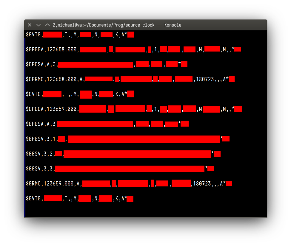
the output is apparently in the NMEA 0183 format, after looking at some documentation, it appears that the $GPRMC “Recommended minimum specific GPS data” contains the date and time, and the gps sends me one of those every second, so i only need to parse those.
and by “parse” i mean:
- find a
$GPRMC,³ - get the next six digits for the hour/minute/seconds
- skip until 8
,s get read - get the next four digits for the day/month
- you’re done! who needs to verify checksums?
formatting of the date
now that the code can read the date, and after some very sketchy timezone & DST logic, i need to display it to the screen, problem is i like seconds but the display only has room for four digits, so i came up with the idea of having the clock be upside down⁴ and using the two edge dots (which are individually addressable) indicate which quarter minute it is ( ⠄⠅⠁)⁵.
since i’m cool i also added a 12-hour mode via some #defines in the main.c file, with an AM/PM indicator using the extra dot character, as well as options to un-flip the display and to hide the leading zero in the hour ( 6:55 instead of 06:55)
all done :)
oh yeah also i published the source code so that this doesn’t happen again.
-michael